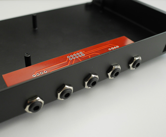
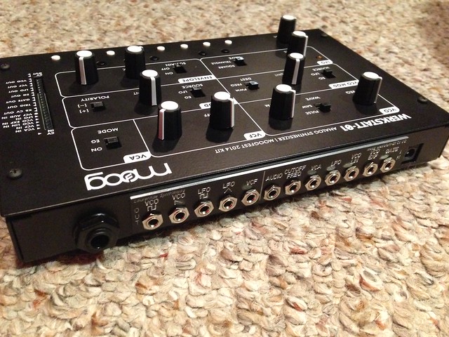
Here’s my Werkstatt finished (sorta) with a custom jack panel. I’ve added a voltage follower circuit to buffer incoming gate triggers to the envelope generator. VCO EXP IN, VCF IN, KB CV OUT, and EG OUT are routed directly to the header points. VCO out is normaled through output jack back into an additional mixer circuit along with the Audio Input. This makes it possible to either route the VCO through modules and back into the filter or bypass the VCF and VCA. I think this is how Steve Dunnington designed his audio input on the werkstatt prototype. The diode clip switch bypasses an added distortion circuit inserted between the VCF and VCA. The diode clip uses a pair of diodes to ground then goes into an additional opamp circuit. Because of the positioning of the jacks, i short changed the amount of usable space on the experimenter pads.
The components are cramped together and i had to place components on both sides in order to make it all fit. In hindsight, i’m not sure if I would recommend adding the jacks to the back panel, because there’s not a lot of room to spare between the PCB and the case. The right side of the case would have made more sense, but the back seemed more “moog”. This was a bit of work, but completely worth the effort to make the Werkstatt part of my modular rig.
Really nice work and answers a question I had about the patch section: no gate input! How strange… Also, when I use the envelope from my Pittsburgh SynthBlock I just get a ‘tick’ not the full envelope. Is there a publish spec for the voltages of each in/out of the patch section?
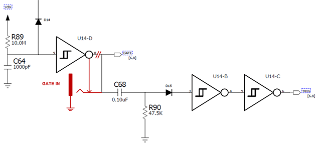
@peff, I borrowed your Gate IN voltage follower idea. If anyone’s interested, I drew up a schematic of what to do to get an external Gate IN. It’s fairly simple, but you will need to cut a trace for it to work properly.
I’m kind of an idiot savante with this stuff. I really want to add a few mods but need someone to spell it out for me. What I would like is to add a gate in, gate out, midi in, audio in and a permanent ground. Is there anyone who could walk me through this stuff.
The follower isn’t necessary. Just a cationary addition really. I’m working on a PCB with SMD parts that’ll solder right to the kludge area, so adding one is no biggy. Hopefully (before Knobcon) I’ll get it done and have some needed mixing options (VCO > Filter, Audio IN, which will double as an Overdrive amount & a master out vol pot). Good question though. Always seemed a bit odd they didn’t offer a Gate In on the patch header. Oh wells.
A little bird told me (although it’s usually not standard practice to send a control signal to a control signal output) that you can send a trigger to the GATE OUT and it will work as a GATE IN.
yeah, looking at the schem, that’ll work as there’s no diode at the gate out and it’ll pass the signal through to create the trigger too, but I wouldn’t advise it. Could run into some issues if hitting the out with a signal in and pressing the keys at the same time.