Can anyone open the back panel of the OS and take a picture of the board? Im curious to see how different it looks from the digitized brain of the Performer series.
Eric
Can anyone open the back panel of the OS and take a picture of the board? Im curious to see how different it looks from the digitized brain of the Performer series.
Eric
It is not a picture from the OS…but i took this picture when i visited RL for my Voyager SE mod upgrade… ![]()

I got sent this at my myspace

Let’s try a side-by-side comparison:
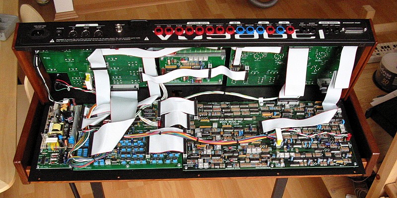
It sure looks empty, eh? Looks like you got boards
in back of the front panel to distribute control signals
from the knobs, and the CVs coming into the back
of the synth, to what I believe is the analog board
on the bottom right. And over to the bottom left,
it looks like you have the power supply.
That’s pretty much it.
I also noticed that there are keyboard gate and CV
outputs available. That might’ve been a nice addition
the Voyager as well, in case you didn’t have the breakout
box. I’m also kind of surprised to see that the 12v
BNC connector is missing for the gooseneck lamp!
Oh well, at least they look like they’re built to last!
I could TOTALLY fit those color changing circuits in there, if the power supply could handle them. ![]()
I don’t know, I think the touchsurface is digital too.
If you have a ribbon controller and you run your finger across, you get a smoothe glide in the oscillator, much like a fretless bass.
With the touchpad CV out to the Freqbox Freq in, you get a zippering effect. SOmetimes you can hear this on the filter cutoff on some patches.
And sometimes I can hear this on the mod wheel, if it is controlling pitch.
Man you could totally Mod the crap out of that OS. You coudl probably install a sequencer board in there, with a breakout box…something not too spacious. Wouldn’t that be the bees ankles?
Eric
It depends on how much the power supply can handle as to how many mods you could put in. If it’s the same power supply as the Voyager Performer, then you have lots of current draw to play with! ![]()
Normally it is good behaviour to let people know where you got a picture from, if it isn’t your own one. And in this case it is my picture of my Voyager in my flat.
http://till-kopper.de/voyager.html
BTW:
here is my Voyager’s digital board with the 3.x hardware field upgrade:
http://till-kopper.de/voyagers_inside/Moog-Voyager_3_hardware_i.jpg
I also have the 3.x hardware field upgrade in my picture…only you won’t notice this as RL used the old PCB and only changed/added the memory chips.
Apologies, Till.
I did link it before, and referenced you as well. Just didn’t think to do it this time.
Tut mir Leid.
Isn’t it great … we can talk together or see photos even when we’re living in complete different areas like Netherland, New Zealand, USA or Germany?
I like it ![]()
Even Russia, even if we’re frozen a bit ![]()
Greetings to Russia!
I like those jack leads, nice and low profile, look like they’d put less stress on the sockets. Where’d you get ones like that? They’d make me less worried about the cheapo jacks in the Virus…
Those jack leads are from RL’s test setup…better ask him about where or what brand to get them.
Hi Richard,
these leads are made by myself and the phone plugs are the cheapest stuff which you can get to be sure that the Voyager even works with those ![]()
Thanks for posting these pictures - very interesting!
Can i just ask…
What are the maggot shapped things? transistors?
Why do some of the capacitors bend over like that?
What exactly are the black chips? IC’s? Like a curtis chip?
Is this design considered to be discrete or chippy?
Thanks
DS
I don’t know…you can look on a basic electronics site to find out what each one is.
But NO THEY AREN"T CURTIS CHIPS. lolol
Curtis doesn’t take voyages.
The yellow maggot-shaped things look to be resistor banks. Why, I dunno, as there seem to be plenty of resistors already. The IC’s are various things, like op-amps and the like. THERE ARE NO CURTIS CHIPS IN A MOOG! ![]() How DARE you spew such filth on these forums!
How DARE you spew such filth on these forums! ![]() These circuits which you see are not discrete transistor, otherwise there would be no IC’s.
These circuits which you see are not discrete transistor, otherwise there would be no IC’s. ![]() None of the capacitors are bent over, so I dunno what you mean, though a couple are leaning due to the crowding of components. The black D-shaped dots are transistors. Hope this clears things up a bit.
None of the capacitors are bent over, so I dunno what you mean, though a couple are leaning due to the crowding of components. The black D-shaped dots are transistors. Hope this clears things up a bit. ![]()
![]()
![]() Curtis Chips…geez.
Curtis Chips…geez. ![]()
![]()