My Satellite has no -9V. IC1 is showing about 19v from pin 12/11 to 7, as expected. C3 has about 9v across it. But C2 does NOT have the -9v as expected.
I have swapped out IC2 and nothing changed. When I test the voltage from pin A8 to ground on main board, I get about 0v vice -18v. It is driving me crazy. Continuity of the cable carrying the -18v is good.
I pulled Q1 and have run through a transistor tester (appears good) and also checked CB and EB using a diode tester (.65v breakdown voltage for each).
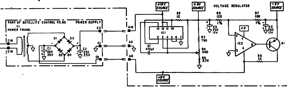
The power supply is providing +/- voltage (about 24v) and the regulator is making +9v. IC2 does have 9v going into pin 7. Voltage across pin 4-3 is about zero.
I feel like I am missing something fundamental. Any ideas on troubleshooting? Workarounds? Anything? Thanks!
I did some repairs to power supply- soldered the molex pin block pins better which 4 had visible cracks in the solder on underside of the pcb, resulting in voltage output problems. I replaced wiring that still had electrical tape on it (probably from 1974!) in the main leads to the transformer. One solder joint even broke while removing tape. Now it has good joints and heat shrink tubing. All voltages are good coming out of the power supply and into the molex plug (verified by back probing at both ends of cable). But here’s the kicker, as soon as I plug in to the main circuit board, the voltage goes from -25v to -5. The positive supply goes from +25 to +18v (which is fine- that part of the voltage regulator circuit works properly). The -5v is the problem.
I am trying to figure out where the voltage is going. The case only has about 0.3v on it. If I pull the IC responsible for converting to -9v, I have the same readings of -5v as soon as I plug in the cable from the power supply to the main board.
I am currently looking for a high-resistance short to ground. I’m hunting for any shorts between wires in the molex bundle. Any thoughts on troubleshooting?
From the Moog Satellite service manual: No regulated -9 volts: load exceeds 50 ma. Measure resistance of -9 volts to ground, nominal value 1000 ohms. Also check C2.
So there might be a short somewhere down the -9 volts buss, or a component pulling more current than normal.
Op amps are known to fail after many years. Especially old 741 and 1458.
I found that IC13 (a 741 op amp) was super hot and connected to the -18v source used by the -9v VR circuit. Pulling it fixed the voltages, but I wonder if the IC failed or if something CAUSED it to fail. I guess I will find out soon enough 
So you were right- heat means drawing too much current.
Back in the days of those machines, the manufacturing process of ICs wasn’t as sophisticated as today. I’ve seen my fair share of blown/shorted out 741, 1458, and 4000 series logic gates in computers. Also be on the lookout for Tantalum capacitors which tend to short out and often cause damage in PSU or elsewhere.
I’m glad you’ve found the culprit.