I have an RME and would like to know the pinout for the CV expansion sockets on the back of the synth. Has anyone figured it out?
Alternately, could someone explain why I should need to buy a VX-351, rather than making a breakout cable myself? Are extra electronics required in order to get standard CV voltages out of the voyager, or something?
Does anyone know what the pass-through board that you install between the voyager and the DB25 socket (in conjunction with the VX-351) actually does?
I’m sorry if my question offended you, but I do think it is a legitimate question..
Since I have the RME, I don’t have a use for several of the connections on the expander box. I also don’t really want a breakout box that has multiples or an attentuator. I would rather just have minijack patch cords come out of the back.
Additionally, as far as I know, there is currently no expander available for the input connector on the RME; so making my own is the only option.
If Moog Music is not publishing it, someone will try to find it by testing the sockets pins one by one. And he/she will publish it somewhere on the internet.
And the tiny little board that needed to be fitted inside the Voyager is populated only by a few decoupling condensators. At least, that is what the board looks like to me when I saw it once. But I am not a technician at all.
Was there ever anyone in the past 10 years who figured out the wiring ? Assuming inside it’s all passive, probably (hopefully) even not any components, and the DB25 is straight. Since having really true lack of space and not needing 1/4" jacks, thinking about making a DIY 1U rack module with 3.5mm jacks and a few simple small pots for the wheels. Lots fo stuff uses the small jacks now. That will save another 2U and about 600$. A pin out definition of the I (XV-352) and O’s (XV-351) would really help. Maybe someone like to open up their XV to see inside.
IIRC this list came from a thread somewhere in the forum here. I have a handwritten copy. Also IIRC I tested these connections way back when. If anybody has corrections or additions by all means modify this list.
VX-351 pinout:
Top Row L>R pins 1-13
1: Common
2: Touchpad Y-axis
3: Touchpad Gate
4: Keyboard Velocity
5: Keyboard Gate
6: Pedal Mod 2
7: Mod Wheel
8: Busses- Pedal
9: Envelope Volume
10: LFO Output- Square Wave
11: S&H Smooth
12: unknown/ not used
13: unknown/ not used
Bottom Row L>R pins 14-25
14: Touchpad X-axis
15: Touchpad A-value
16: * Keyboard Pitch. Not recalling why I flagged this with an asteric
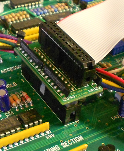
I have just added the little board inside my Voyager and the components look very much like SIL (Single In Line) resistor packs/networks. The PCB silkscreen labels them as ‘RN’ for Resistor Network. My guess they are there to protect the Voyager CV drives from any short circuits that may occur outside the Voyager by putting a smallish value resistor in series…
Good guess… being an EE that would be a good protection scheme.
Back in the Trumansburg days, David Borden was a local musician who was invited to play with the modular in the studio at the RA Moog factory. He blew a few modules and was really embarrassed, but the staff told him not to worry. They wanted to know any and all failure modes, and wanted to modify the circuits to protect them. He didn’t realize at the time that he was their beta tester.
I’m sure that experience did not escape Bob when he designed the VX-351.
It’s not passive, there is a driver circuit to boost the Pitch CV and a few other components, I never bothered to trace it.
Click on the Flickr! link in my signature for a decent pic of the internals of the VX-351 (and read the description beneath the photo). If you want a higher res photo or a pic of the back, PM me but I would suggest just buying it from Moog or buy a used VX-351. Doing anything else is a fools errand (more trouble than it’s worth)
Fantastic to have the ones for the 351. Where is that IIRC ? Is there lot of stuff there? Maybe there is something for the 352 I/O 's (I have an RME BTW)
Bought the VX351/352 expanders for the RME though the amount of $ turned my stomach around a bit. Hope Moog will publish a (service) manual for these items now that these items are out of production. The instruction sheet did not mention that little board does not have to be installed in the RME but it was stated in the manual.