I answer myself now
My second problem - the slow keyboard response and unability to play staccato nots - is solved.
I simply lowered R47 to speed up the discharging of the parallel capacitor to ca. 80k - voila !
But the retriggering mod is still not working.
I doublechecked all the wiring, replaced the 1μF capacitor with a film capacitor, but still no success.
It works a bit better now, it is retriggering if the distance between the notes is high (more than an octave) , and it retriggers only in one direction: playing low notes simultaneously to held high notes does not work, the other direction works if the the distance ist large enough.
does anybody have experience with that mod ?
any ideas ?
thank you very much !
OK, here comes part 3 of my monologue.
the good news:
I think that now everything works as it should.
The problem, that the retriggering functioned only with larger note distance, was due to the fact that in the diagram on page 1 of this thread a wrong value for R2 is drawn. R2 should be 10k and not 100k (as in the original Ricard Wolf circuit - http://machines.hyperreal.org/manufacturers/Moog/MG-1/mods/MG-1.multitrig.mod.txt).
with the smaller value for r2, retriggering now works.
However, with the following restrictions:
Due to the High Note Priority multitiggering works logically only in one direction
Also when releasing a key is re-triggered, as long as other keys are pressed
This feels strange when playing, you have to get used to it.
It has now become clear to me that it has to be this way and that it can not be otherwise. I’m not sure if I want it that way. Maybe I just keep the Continous Glide Part - and leave the synth in single trigger mode.
But it would be good if the schematic on page 1 were corrected (R2 = 10k)
Has anybody else compleated the minimoog filter mod? After instaling this mod, the peak emphasis does nothing untill it is turned up to about 90 %, then quickly goes into self oscilation. Im not sure if this is normal. 9apps cartoon hd
Hello-
This is my first time posting on the forum, so please forgive me if my forum etiquette is off.
I recently acquired an MG-1 and have done a few mods:
Changed resistor to detune full octave (tone source 2)
Removed resistor so Output is Louder
Added LFO mod for .25 and .5 LFO speed.
I calibrated the oscillators, however, when I attempted to calibrate the filter (according to service manual), I suspect something may have gone wrong. When I very first started the calibration process per pg 18 of the service manual, I could hear an oscillation (i think the self oscillation of LFO), and I proceeded to step 5: adjust emphasis trim at pin6 of IC U1012, when I had my multi-meter to check the pins and adjust emphasis trim pot, at some point the oscillation I heard disappeared, and no matter what the trim pots are for emphasis, or filter scale, or filter cutoff, I can no longer hear any kind of self oscillation. Furthermore, the slider for ‘Peak Emphasis’ doesn’t seem to have any effect on the sound.
Ive checked the IC at U1012, and I believe it is working correctly, but Im not 100% sure.
Does anyone have any tips on using multi-meters to probe ICs? …or any other likely culprits that could cause the ‘peak emphasis’ to no longer have an effect?
…and just to be sure, when the manual says the filter should self oscillate, does that mean it should be audible to the human ear (like the tone oscillators?), or is it something that can only be measured with a DMM, Oscilloscope, or other tool?
I have an answer to only one of your questions.
When one says a filter can self-oscillate, it means that the resonance, aka emphasis aka q-factor can go high enough for the filter to produce an oscillation pitched on the cut off frequency. And given the cut off frequency range, you guess the said oscillation, which can sound as a larsen, is audible, yep.
I’m sure some others Moogists will chime in to help you with the technical stuff
Thanks for getting back. I’m no sure that I’m getting no self oscillation from the filter. I’m looking at swapping out U1009 IC for a new one. And updating the peak emphasis slider with a new one from syntaur.
According to the schema of the service manual the MG-1 uses a standard circuit to control emphasis and self oscillation. The resistor values of R93 and R100 are added. If both are turned into direction of zero ohm at some point the self oscillation must start. U12 adds the two phase halfs of the ladder output as a difference amplifier, and the amplification factor is determined by R99 (75k). If R93 and R100 are lowered to zero (which means maximum emphasis) and no self oscillation starts you can increase the value of R99 to lets say 100k or more. This increases the ladder output amplification accordingly. But you should check the output of U12 (pin 6) with a scope first, NOT WITH A MULTIMETER! Perhaps you killed U12 with that. The filter itself continues working, but the emphasis and self oscillation is dead of course. If no output can be seen WITH A SCOPE at pin 6 you should replace U12. I’ve seen such faults before.
My tip is DON’T USE A MULTIMETER! You can shorten IC pins with that. The neighbor of pin 6 (output) is pin 7 (+12V power supply). I don’t know what happens if you shorten the output of U12 with its power supply, but that can’t be good. Use an oscilloscope instead. If no emphasis happens any more, you probably killed the 741 opamp (U12), is my assumption. But this is a standard component, easy to obtain and easy to replace.
Analogmaster-
Thanks for getting back to me. I had no idea about the risks of using a multi meter on the synth. I’ve got a scope I can use from here on out. Ur appraisal of shorting U12 while using the multimeter matches my experience. I’ve got a replacement chip I’ve ordered from Jameco and should be here on Wednesday. I also ordered a replacement for U9, and a new slider for the peak emphasis. But I’m gonna start by replacing U12 with the hope that solves things.
When using a scope on the synth are there any best practices for getting measurements?
Thanks for the quick reply and I’m feeling a lot more confident about the next efforts I’ll be making thanks to u.
One other question I had was about the keyboard current source adjustment on page 16 of the service manual. I’m able to adjust hi end trim R2057 for 2.85 bolts with high c pressed, but when I hit the low F and adjust low end trim R2051 for 0 volts, I’m not able to get 0 volts. The float I can get is about 150 mV. The low end trim won’t go any further.
Is it possible a neighboring resistor or other component t near the low end trim is bad?
The only way I can get it to 0 volts is if the hi-end trim For high c is less than 2.85v. More like 2.65v in this scenario.
Thanks for your compliment but I am just a monster not a master
I did not get the point. Why do you want to replace the transistor array (U9)?
…and why this? Does it have another value?
You can check with a scope first whether a replacement is necessary or not. Measure the amplitude / signal of the filter output signal at pin 6 of U12 first. According service manual this should be a +14mV/-12mV signal.
Don’t touch any components with your hands while the synth is powered on / power cable is plugged in
Find a proper place to connect the ground clamp of the measuring head
Be very careful not to short IC pins when touch a pin with the measuring head
Pre-select 10mV/grid unit vertical maximum (5mV would be better) and about 10msec/grid unit horizontal on the scope to see a proper result when measuring pin 6 of U12
If nothing appears on pin 6: Pre-select the scope for 5V/grid unit and measure pin 7 for +12V to be sure that U12 is power supplied, meaning if the power supply is present and no output at pin 6 then U12 is definitely dead
You are welcome. If there are more questions / points to discuss don’t hesitate to ask. When I started in engineering synthesizers people helped me as well.
analogmonster -
Replacing U12 with a new chip worked! The peak emphasis is now working again! Thanks for your feedback.
One thing I have on my ‘mod wishlist’ is adding an external input for VC to control the LFO. I see some mentions of that on the forum but no real specific instructions.
Does anyone have any schematics for adding a VC input for the LFO?
That’s cool So you repaired an original Moog synth, which I consider as great success, as these analog veterans deserve to be kept and “cherished”.
I agree. CV controlled LFOs are magic. And if two VC-LFOs control each other, it is even cooler LOL. I emulated ratcheting with an VC-LFO controlled by an EG. Listen to my track You from time point 5:13, there you can hear it.
It depends on the LFO circuit of course, where you have to feed the CV in and how you feed it in. I did this for my Formant LFOs, see also here: VC-LFO
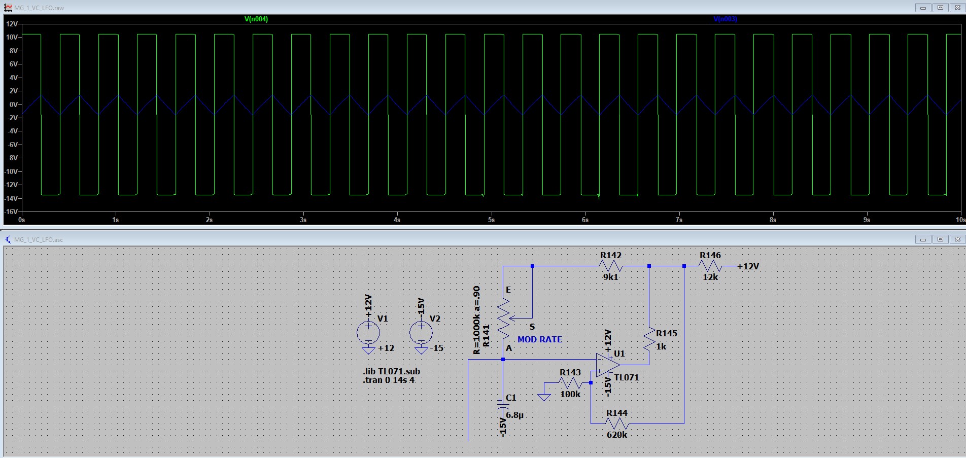
For the MG-1 LFO you must feed in the voltage at the connection between R142 (9.1K) and the MOD RATE slider R141 via a 1K resistor, I assume, but I will check it with LTSpice and communicate the result here.
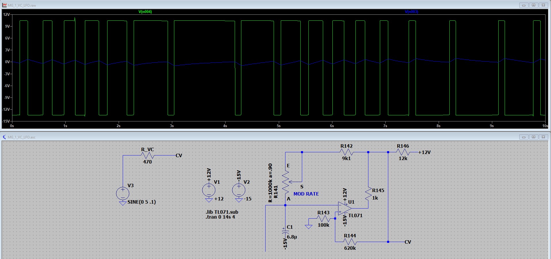
I was wrong. The MG-1 - LFO is current driven, not voltage driven like other LFOs (like my Formant LFOs I modded with voltage control). But you can add a CV between R144 and R146 via 470R resistor in your MG-1. See the LTSpice results of the original MG-1 LFO and a VC variant at MG1_LFO and MG_VC_LFO. The triangle and pulse LFO outputs change in frequency when an e. g. 5V sine is added to the point I mentioned above, but as side effect the LFO amplitude decreases a bit. To compensate that a more complex circuit would be needed or better a voltage driven LFO, no current driven LFO.