well, I’d like to go on with my mods and want to ask if there are people here who know about the Sync-installation of the last 10 Minimoogs with the golden badge and might offer me some pics so that I can get an impression what it looks like and what functions there are…
If there won’t be anybody there who’ll teach me a better way, I’m going to sacrifice one of the two DC power supply jacks to prevent the housing of being damaged by drillig holes into. The second jack I’ve to keep for my S&H generator.
I’m going to put at that place two toggle switches, one for switching Sync on and off, and the other one for switching the Filter Contour on and off.
I think more than this needs not to be done. The electronic work for my tech is just a walk in the park…
I don’t know about the Moog factory Sync mod, but I’ve done the one found on the web myself with ease.
As for the S&H, I’ve added it to my Korg Mono/Poly using this neat little 8 pin chip called LF398 (Sample-And-Hold-on-a-chip) easily found inexpensively and requiring only a minimal amount of external components.
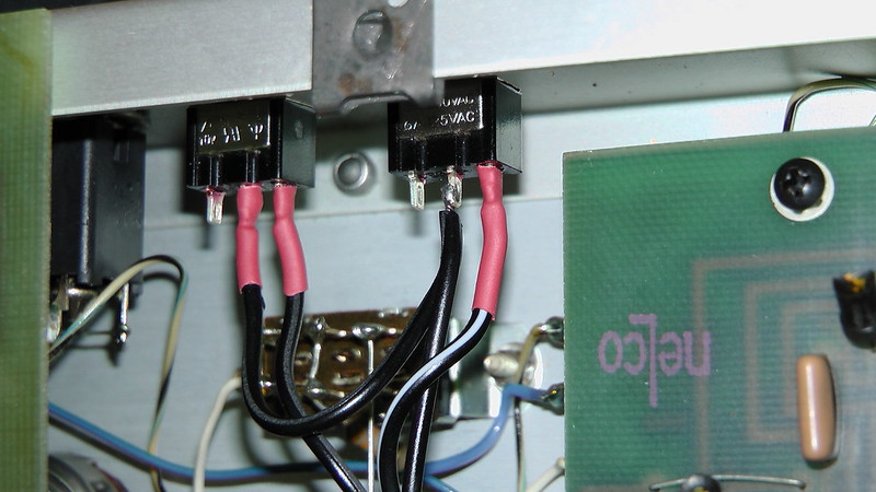
Below we see the black wires tied together with red tie-wrap going to the oscillator board:
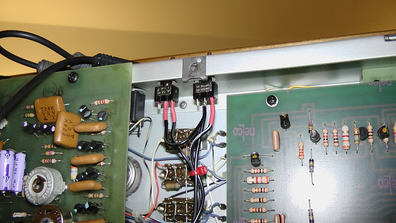
The two chromed small toggle bats (the one on the right is VCO2 and the one on the left is VCO3, both for sync on or off, shown here in the off position):
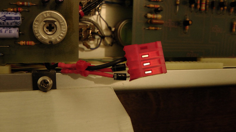
Here we see the two diodes (resistors are inside the red shrink-wrap (the connector is optional for servicing convenience only):
Close-up of the wires connected to the toggle switches:
Thanks Alain, for your suggestions and the subsequent pics
I googeld for the factory sync by myself but obviously it`s a hoax as the pics of one of that brass badged didn’t show any mods in details outside. There’s obviously only an additional CV output and a “Scale” button, don’t know what for.
The first time of that strange sync mod I’ve been told from the most well known synth dealer here on this continent. He had one of these last 25 Minis in stock, but did’t tell the truth…strange.
As for the S&H generator I need no mod to do, as I’ve the original MOOG 1125 S%H module. I only wanted to tell that I need the second power supply for feeding it…
I decided now to use a three posistion toggle switch, like on the T2 module…OFF, ON, and Contour…
Thanks for that, i will try it when I get a chance. Where did you get the switches, and will any do? I am guessing you have the new osc board, as do I with my 12k serial?
Nop, mine is the middle model serial in the 7000. The most common. If yours is serial 12K it’s most probably equipped with the most recent, newer oscillator board.
In that case, you simply need to look for the “sync mod for new osc bd” just below on the Synthfool page link I gave in my last post.
It’s a little more involved since you need to build a small two transistors (one NPN and one FET) circuit, instead of simply two diodes/resistors. Really nothing a trained tech, or experienced electronics hobbyist can’t do.
But most probably not a novice.
Sorry.
The 2n3904 is the NPN, whose base connects to IC8 (7th pin?), whose collector goes to +10 and the base of the FET, emitter goes to a resistor then to -10 and SW1 (the switch?). The FET source and drain connect to Q9.
Shouldn’t be too hard, and the worst that can happen is it blows up, never to work again, and I am left with a software emulator, but it never really cuts it and I end up selling myself on the streets to buy another. Before I save up enough, though, I see someone selling a mg-1, and can’t live another day without a moog, so buy it, and try to mod it and it blows up. Thanks for the advice.
I took a beginner’s course, but it’s been a while, and had to look it up. But i have no idea where the switches are in your mod. mine looks like it has one switch.
In the diagrams at synthfool.com, the old oscillator schema shows a sync mod where you can sync both VCO 2 and 3 to VCO 1, hence the two switches. The schema for the new oscillator board only shows sync for VCO 2->VCO 1.
I guess one could adapt the same solution for VCO 3 as well though? Question is, is sync for VCO 3 worth it? I haven’t been able to find any demo of it. Someone here posted one on soundcloud a while ago (wasn’t that thealien666?) but the link seems to be dead.
In a sync configuration there’s always a master and a slave, or slaves in this case. Whilst it is possible to choose a different master than VCO1, the ability to select another one would definitely complicate the sync circuit, though not impossible to do.
In my config, VCO1 is always master, and VCO2 and 3 are slaves that sync to the master.
I had a pretty long discussion yesterday and I finally cannot see clear with your mod.
Obviously you’ve synced all three oscs. But how does itr work ???
If you’re using additionally osc 3 is the second sync-synced. If yes, might be pretty interesting…
And what are your other routings ? Do you also have routed the Filter Contour on ?
It’s even possible to rout the 3rd as an LFO. But then the Mini will look inside like the Memory
BTW, I’m pretty sure that I`ve the new board inside as mine is under 13000 below…
As I wrote in my previous post, VCO1 is always the master, to which VCO2 and/or VCO3 synchronize to. Simple as that.
In other words, no matter what the frequency of VCO2 is, it will be restarted by the frequency of VCO1. Same thing for VCO3 independently of VCO2.
It’s a fixed configuration, so VCO1 could never be a slave, and is always the master.
That’s why the “sync effect” will always work best when VCO1’s frequency is lower than that of the slaves. Moreover, the “sync effect” will only be heard when changing the frequency of the slaves manually, since there is no envelope, or LFO (VCO3 used in an LFO configuration) routing to the pitch of either VCO2 or VCO3 independently of VCO1.
BTW, for those with a newer osc board (the one with more than 7 adjustment trimpots), I don’t know of the sync mod shown on Kevin’s Synthfool page for it would work. As Kevin himself wrote a disclaimer that he did not try them out himself. I just know that the one for the “regular” osc board works fine in my Mini.
Top one in the picture below is the most common, below that is the “newer” version.
Actually it might look more like this one (note the ua726 round chips instead of the DIP package of a CA3046 with a Tempco glued on top, as the ua726 as already a integrated thermostat system inside it)
But you get the idea that it has more than 7 trimpots also.
Thank you SO MUCH
The discussion will go on. My tech stays very cool about the mod of the newer board. He said on the iolder one there’s more to know and not so easy. I cannot comment this.
But with your detailed descriptions we’ll gonna succeed at the end…Wonderful
Also be aware that, since the original VCO circuits were not designed to be hard synced, the behavior of the “hard sync effect” might not be as smooth as on synthesizers with that feature integrated into their design.
Meaning that, when the slave oscillator (VCO2 or 3) is “restarted” by VCO1’s frequency, there is a very brief delay until it starts oscillating again (very noticeable when VCO1 is set to the Lo range). The result is a sort of “harsh” or “crude” hard sync effect at audio frequencies. But very usable nonetheless.
Fine, I’m going to add this.
But Ive also to tell you,that my tech is some kind of weird of your former description of the 3 oscillator mod (???). He says that your configuration makes no sense and theres no tonal benefit to achieve.
Well, Im still not satisfied with this judgement and will print your description and take it home to talk about again. But he and I were still have the same opinion that my Sync-Synced (Double Sync Version, the synced oscillator 2 is the provider and Nr. 3 will be the double synced)… might be interesting.
But it’s questionable if we ever try, as ther`re SO MANY wires at the end and may lead to confusion…
Well Im thinking about, and I'll dicide for the simple solution as I described initially, 2 oscillators with the Filtor Contour, but independently !!! regulated with a pot. "Sweep Depth". Today I bought a pot with a intigrated switch, so that I don't need an additional toggle and can use that small place best after unscrewing one of the power supply jacks. Thats it.
The electronic mod Ill do also by myself with instructions of my tech on the phone. He said he also doesnt care of that bug you’ve told about, as he absolutely does know how to do the job precisely.
The point of having both VCO 2 and 3 independently syncable to VCO 1 is this:
VCO 3 can be used for frequency modulation of VCO1 and 2. You might like to be able to do that while VCO 2 is synced to VCO 1. So that’s why you might like to have only VCO 2 synced to VCO 1.
VCO 3 can be set to a fixed frequency (OSC Control Off). Syncing VCO 3 to VCO 1, with VCO 3 set to a fixed frequency, can create unique timbres. So that’s why you might like to have VCO 3 synced to VCO 1, either on its own, or with VCO 2 synced as well.