Looks like the UJT reset pulse is a bit extreme on that module. It’s an anomaly that is known with ramp waveshapes of 901 VCOs. How does the ramp waveshape compare with the others?
Just a note (I should have made this more clear in the original post)- the changes in frequency are introduced by me, the oscillator itself is pretty stable. (I did this to show how the oscillator responded at different frequencies.)
I’ll see if I can get a ramp sample later on today.
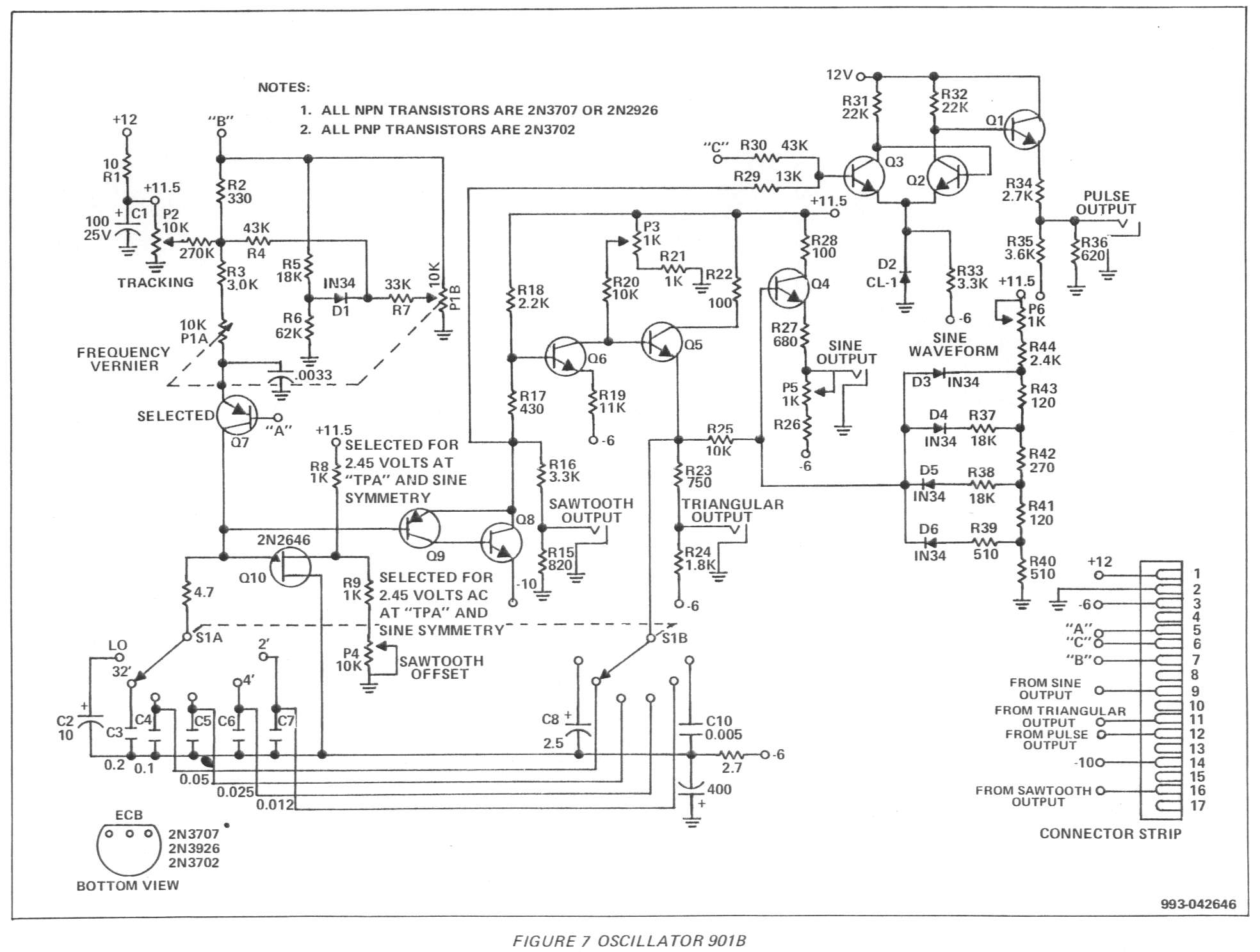
On the 901 the sine is derived from the triangle wave which is in turn derived from the sawtooth wave.
The triangle is formed by inverting/mirroring one half of the sawtooth wave cycle.
From your scope trace, the triangle is not quite symmetrical - i.e. the circuit that inverts/mirrors the sawtooth is out of trim and is kicking in a little after the peak of the sawtooth instead of at the exact peak.
Look at the schematic and adjust the trim pot P3 and observe your scope for triangle symmetry. If that doesn’t fix it, adjust trim pot P4 (sawtooth offset) also and then go back to adjusting P3. If that doesn’t work, check the 1K resistors R8/R9 and replace if necessary to get the recommended 2.45V at Test Point ‘A’.
It’s a great design. Simple, economical and yet so effective. Amazing what Bob & co. could manage to achieve with a handful of discrete transistors back in the day.
Did you use the transistors as spec’d or just any general-purpose signal transistors (BC55x etc). I might have a crack at one of these myself.