https://www.youtube.com/watch?v=qzUYwTyRaPg&ab_channel=noddyspuncture
How is the temperature stabilization done? Not with the diode arrays, I assume. And is the dual pot solution of the frequency vernier changed also?
Yes, the complete oscillator section of the 901B is discarded so the dual pot is also gone. The new oscillator is on the piggyback daughter board. The stabilisation is done with a tempco resistor and the whole expo convertor is redesigned and now lives in the oscillator… it’s all rather like the 921’s ended up being - only without any IC’s… ![]()
Ah, that’s good ![]() Is the wave shaper also redesigned? That would be a pity, as the old circuit added such a nice and smooth buzz to the waves I like very much.
Is the wave shaper also redesigned? That would be a pity, as the old circuit added such a nice and smooth buzz to the waves I like very much.
This is good . Are you planning to make the information available ?
ie circuit schematics etc ? I guess you put a lot of time and effort into this Can you tell us where the original information was located ? I can only think you had access to Keith’s stuff…choose what, great effort.
Yes the wave shaper section is indeed retained - obviously Bob had the same opinion as both you and I… ![]()
No I’m keeping it safe, as I promised my source.
I’m also building a full ‘preset box’ system based on Emo’s original one to interface with my Model 15. And again, I’ll keep that info safe too. In fact, there was a lot of it missing and I had to experiment with it and work it out myself over the years..!
Okay..keep safe !
That is an awesome project!!
Congratulations on getting it figured out & working
It’s also a great tribute to both Keith and Bob
RIP
It sounds like an interesting historical document, why must it be shrouded in secrecy?
Today I finished the preset box button selector unit… and it’s working nicely..! ![]()
Looks slick!
That is a crapload of wiring…
Did Keith’s have 10 presets? I thought he only had 4-6?
He had at least 14 or more at one point. He has two preset boxes in some photos around 1972/3. Maybe he used the Moog a lot more around then, he did make lots and lots of different sound effects in the middle of Tarkus and Pictures around that time as can be heard on the boot-legs.
His original box had 7 or 8 loaded - you can clearly see not all slots are filled in photos. In '77 he had the new revised ‘module’ type preset enclosures, although there will have been a master module which they all connected to somewhere.
They had two presets each and there were six of those ‘modules’ in some photos, making 12 presets. In later years and up to today with the restored system at the museum there are just 5 of those ‘modules’ making 10 presets. I decided to go for 10 as the steel box I had and the size of ‘cards’ it could take dictated it. ![]()
So, basically having now built and interfaced everything with regards to the Moog Modular preset box - (except the preset cards and also the 901’s, I’m still waiting on the FET from the USA for those…) - it occurred to me that I should maybe test out a few of the features. I could do that by replicating what a card would do… basically connecting points to ground and applying some voltages here and there so I picked the lines into the 921B oscillators which control the footages. I also picked one of the lines into the 921A controller for fine tune and then I found the two lines which control the mixer inputs I’m using. I fed a sawtooth from the first 921B osc and a triangle from the second into the mixer, The control here is just on & off… or ‘sounding’ and ‘muted’. The card will allow for in between, so voltage controlled ‘mixing’ will be possible. I used my little breadboard and pins to change the settings. The functions I’m not changing here are the filter cut-off, the resonance level and also none of the EG parameters. Adding those to this demo would have been too big a job and as I’ve already had problems with those bundles of wires shorting, it wasn’t worth the risk..! And also as those are a massive part of the ‘perceived effects’ on a patch change this demo is quite a simple and basic one - just to confirm my wiring is “something like” and also to give you an idea of what this thing will be doing.
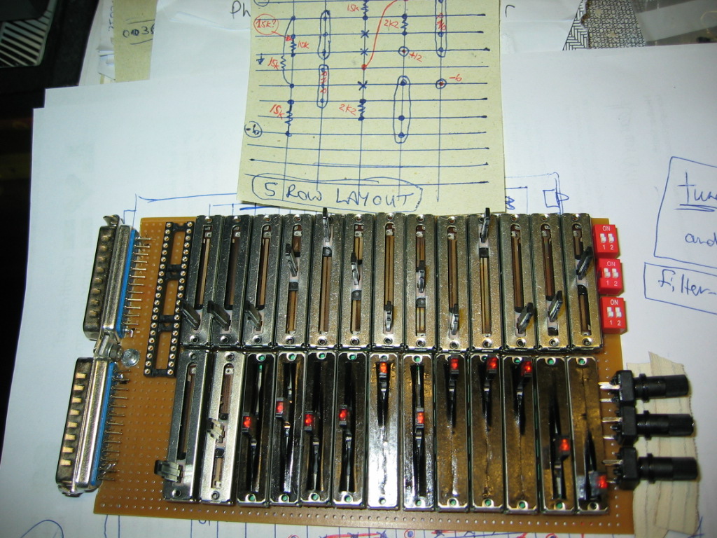
Thought I’d try a rough layout of the bits which will populate a preset card.
Ooooh… it’s looking a bit cramped on there, even more so when you consider that I also have to fit a small (6 resistor and 4 transistor) circuit into that small free space bottom left.
So I had to do a quick redesign of that circuit’s layout and it looks like I’ll be able to do it. I mistakenly labelled the drawing ‘5 ROW’ - when it it’s actually ‘5 COLUMN’.
I’m sure I know where that 901B updated design came from. In late 1970 Jim Scott and Bill Hemsath were designing the first two Minimoog prototypes. The first two designs used surplus or junked circuit boards including 901A’s and 901Bs that were laying around at the Moog factory. The design team knew that the 901 oscillator was not nearly good enough for the proposed Minimoog and that is when Bob Moog contributed a totally new oscillator design to the project. Most technically minded people know that the roughly 12,000 Minimoogs that were manufactured used either one of two oscillator boards but there were actually THREE oscillator board designs. The first oscillator board was only used in the first 100 or so Minimoogs that were built in Trumansburg, although it was conceptionally the same design as the later two oscillator boards and the 921 series it was implemented quite differently. Try to find R.A. Moog drawing #1441 dated 12/21/70 and you will see what I mean. That drawing, titled “Triple Oscillator”, shows a PNP transistor pair as the exponential converter which sourced current to a sawtooth oscillator that had a rising ramp, the 901B also had a rising sawtooth ramp but used diode strings as an expo converter which wasn’t nearly as accurate as a transistor pair. Although this oscillator had numerous op-amps they were all done with discrete transistors. Because no monolithic op-amps were used the overall performance wasn’t the greatest by today’s standards but it was still a huge improvement over the 901 diode based design in terms of tracking accuracy and temperature stability. I’m guessing that a variation of that early Minimoog oscillator design is what was put into Keith Emerson’s 901s, if nothing else the timeframe is about right. The later Minimoog oscillator board that used a CA3046 transistor array and a falling sawtooth waveform wasn’t released until April 1972 and the board with the ua726 based expo converter was released 6 years after that so I don’t see how those designs could have been used for the 901 upgrade.
About the Minimoog VCOs:
There is a scans of a schematic using a SG3821 chip for the exponential transistor dates 10th April 1972. Drawing number 08-001. Hand drawn.
And of cause, there is the well known CA3046 based design shown in the service manual. This is also hand drawn.
According to a service manual version, the ua726 was built into serial numbers 10175 and above. This schematic looks more modern and uses black labels for the trimmers, pods and switches.
Yes, the 08-001 VCO drawing and the later design using the ua726 are well documented and well known.
Many years ago I ran the service department at a large music store that was also a Moog dealer and I accumulated a large number of drawings from Moog, ARP, and others, all of which I still have. Some of the drawings that I got from Moog such as 08-013 921B oscillator, 08-009 921A oscillator controller and a few others, were sent to me as actual blueprints, most likely printed out directly from their inventory of drawings.
I also have some of what I think might be rare drawings for the ARP 2600, they look like the original circuit design drawings with title blocks and design revisions. The title block show the name of the company as Tonus, Inc. which was the original name of the company when Alan R. Pearlman first set it up. I’ve been thinking of scanning those drawings and posting them in case anyone would like to see them if they are not already available somewhere.
Really enjoyed the KE solo of Tarkus on your moog modular. You sound great and you Modular looks cool as well. My drummer friend Tony Pia played drums for KE before KE passed. Looking forward to hearing more of your playing and pics of your cool modular if you release any more YouTube videos.
Here is Jim Scott explaining how the Emerson 1Ca was an evolutionary step towards what became the minimoog:
Courtesy of EMEAPP