Page 1 of 1
901b VCO calibration
Posted: Wed Sep 26, 2012 3:14 am
by zarone
Hello,
facing the Moog 55 calibration, I read in the service manual: "check sawtooth output for approx. -6dB" and other statements involving dBs.
As an "electronic moron" I cannot figure out what to check. I know that dB are relative parameters, but... what to check precisely in such a process? Are we talking about V or what?
Thanks
Fernando
Re: 901b VCO calibration
Posted: Wed Sep 26, 2012 6:16 am
by Kevin Lightner
Since this is your own system and it otherwise doesn't have any problems, to a certain degree you can ignore statements such as "verify" or "check."
These are often meant for a tech that often knows nothing about a particular module they've received for service.
If you really want to check them, good meters and scopes can directly read dB.
The problem is knowing whether dB is truly being asked for.. which is usually used exclusively for sound pressure levels..or if the measurement is dBv or dBu.
-6dBu is roughly equivalent to 1v peak to peak, but -6dBv is about 1.4v peak to peak.
Re: 901b VCO calibration
Posted: Wed Sep 26, 2012 9:50 am
by MC
Did standards such as dBv or dBu exist back in the 1960s? I know dBm was around back then.
I have 1960s transistor design manuals from GE and TI at home, might check them.
Re: 901b VCO calibration
Posted: Wed Sep 26, 2012 5:24 pm
by Kevin Lightner
MC wrote:Did standards such as dBv or dBu exist back in the 1960s?
Good question. I don't know.
dBm definitely was as it's a wattage measurement used in radio a long time.
As far as Moog modules tho, they mostly ask to verify the core amplitude so waveshapers work within their trim range.
They just want to make sure you can dial in a good triangle wave.
But even working properly (ie: good tracking, waveshapes, etc) the amplitude of 901s can vary a bit.
40+ year old components aren't the sole reason either.
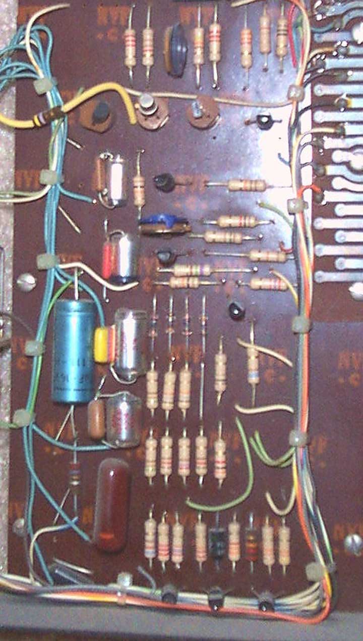
The UJT transistors and accompanying core transistors could vary highly even when new and they define the amplitude and tracking curve.
Transistor selection at the Moog factory was likely the reason those three key transistors got sockets.
Other transistors such as in the sine shapers, were directly soldered in.
Variances on those circuits wasn't nearly as critical.

Re: 901b VCO calibration
Posted: Wed Sep 26, 2012 7:12 pm
by thealien666
Interesting, Kevin. I wasn't aware of Moog circuit boards with socketed transistors... Were those prototypes, or production boards ?
Re: 901b VCO calibration
Posted: Wed Sep 26, 2012 7:32 pm
by Kevin Lightner
Early production.
Later ones had slightly different layouts and standard "glass" boards.
They also mounted the range caps on the board instead of directly on the octave selector.
Re: 901b VCO calibration
Posted: Wed Sep 26, 2012 11:52 pm
by MC
Well I checked my 1969 Audio Cyclopedia, can't get a better resource than that.
The only dB terms anywhere are dBm and dBx. No dBv, dBu, nothing else. dBx was "dB crosstalk", a dinosaur from the transmission industry (I never heard of it).
Even in the "Volume" chapter, VU is the dominant standard. Zero mention of dBv or dBu.
This book has tons of schematics. To give you an idea how old it is, the schematics are vacuum tubes and discrete transistors, and zero nada opamps. Germanium gets equal billing with silicon transistors. That about fits right in 1969.
So the 901b calibration method may be referring to -6dB as a relative drop - but from what reference?
Re: 901b VCO calibration
Posted: Sat Sep 29, 2012 8:47 pm
by Voltor07
MC wrote:
So the 901b calibration method may be referring to -6dB as a relative drop - but from what reference?
I was thinking from the reference of a triangle wave, but I could be, and probably am, wrong.

