Re: racking the fooger collection
Posted: Mon Apr 23, 2012 12:05 pm
Hey everyone I've been pulling my hair out trying to piece this together, I emailed moog and this is what they told me.
Since our Moogerfoogers are designed to work with both passive and active CV devices, wiring them up to a patchbay can be tricky. Basically, the internal wiring of the CV jacks is like this:
Tip - Receives incoming voltage to control parameter
Ring - +5v. When nothing is plugged into the jack, this is shorted to the Tip. This way the Tip is constantly supplied with +5v.
Sleeve - Ground
The problem here is that, in order to have the pedals hooked up to the patch bay, you will need to have cables permanently plugged in to the CV jacks. This breaks the connection between the Ring and Tip and drops the Tip voltage down to 0.
To overcome this, you will need to wire your patch bay jacks so that the Tip and Ring are shorted together whenever there is no cable plugged in. When you insert a patch cable, it should break the connection and replace the Tip voltage with whatever voltage is coming in.
I'm afraid this this as best as I can explain it. Good luck and let me know if you need anything else.
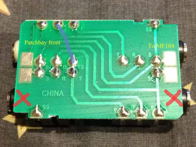
This sound different then the info Ive been reading on here seank, latigid on I have the same patchbay as seank do u think you can help me a little with info on the soldering side of things just maybe explain a little more where I should be soldering the patchbay pcb, http://i43.tinypic.com/2w2hufq.jpg Do i solder to this side or the other side? this is the last thing I need done. help please.
Since our Moogerfoogers are designed to work with both passive and active CV devices, wiring them up to a patchbay can be tricky. Basically, the internal wiring of the CV jacks is like this:
Tip - Receives incoming voltage to control parameter
Ring - +5v. When nothing is plugged into the jack, this is shorted to the Tip. This way the Tip is constantly supplied with +5v.
Sleeve - Ground
The problem here is that, in order to have the pedals hooked up to the patch bay, you will need to have cables permanently plugged in to the CV jacks. This breaks the connection between the Ring and Tip and drops the Tip voltage down to 0.
To overcome this, you will need to wire your patch bay jacks so that the Tip and Ring are shorted together whenever there is no cable plugged in. When you insert a patch cable, it should break the connection and replace the Tip voltage with whatever voltage is coming in.
I'm afraid this this as best as I can explain it. Good luck and let me know if you need anything else.
This sound different then the info Ive been reading on here seank, latigid on I have the same patchbay as seank do u think you can help me a little with info on the soldering side of things just maybe explain a little more where I should be soldering the patchbay pcb, http://i43.tinypic.com/2w2hufq.jpg Do i solder to this side or the other side? this is the last thing I need done. help please.

