Yes, you would be modding the patchbay, not the 'fooger.
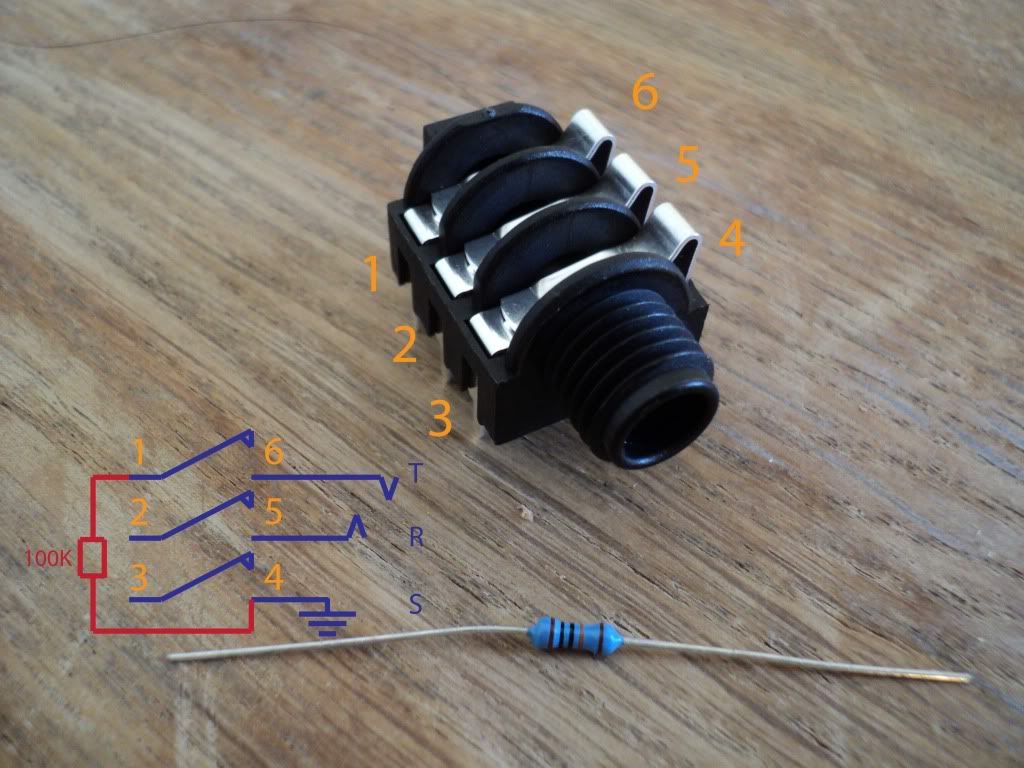
Above is how you would wire a socket. In an off-the-shelf PB the situation will probably be more complex than this, as there are additional traces on the PCB so it "knows" what you plug in and which configuration you need.
The operation is pretty simple: pins 1, 2 and 3 represent the normally closed switch contacts. 6, 5 and 4 are the T, R, S contacts, respectively. When no plug is inserted, the switches are closed and the signals flow to/from pin 1<>6, 2<>5 and 3<>4. When a plug is inserted, the signals instead flow to/from pins 6, 5 and 4 to the T R S plug and are disconnected from 1, 2 and 3.
So for the 104, an expression signal is represented by
6: CV/"resistance" (input)
5: +5 VDC output (supply)
4: ground
And to "normal" your connection, you need to send the signal hitting pin 6 through a 100k resistor to ground, ONLY IF there is no plug inserted. No plug means pin 6 is connected to pin 1.
So connect pins 1 and 4 with a resistor, the input will be clamped to ground when you need it. Insert a patch cable and the resistor is out of circuit.


