Page 1 of 2
Need a cheap way to attenuate a signal?
Posted: Mon Mar 22, 2010 6:28 pm
by Benjamin AM
If you're handy with a soldering iron, you can do it with a pot(50k Lin is good). If not, this passive mixer works very well. I find that it compliments the CP-251 very well.
http://www.sweetwater.com/store/detail/SplitMix4/. edit-note that the pots are audio tapered.
Posted: Mon Mar 22, 2010 7:10 pm
by dave500
Benjamin,
How do you like your CP-251?
Posted: Mon Mar 22, 2010 11:32 pm
by ColorForm2113
Does that little art mixer work well with cv?
Posted: Tue Mar 23, 2010 4:56 am
by varice
Hey, thanks for suggesting the SPLITMix4. I think it could also be used as an alternative control input for Nord Modular synths:
http://electro-music.com/forum/viewtopic.php?t=32424
The specs don't mention it, but I assume that the SPLITMix4 has audio taper pots. Can you tell if they are audio or linear taper?
In retrospect
Posted: Tue Mar 23, 2010 10:45 am
by Benjamin AM
I don't know how I overlooked the fact that the pots are Audio(Log) tapered. Now that you mention this, I do notice that the signal is heavy on the end. I opened it up to see how easy it would be to replace the pots with linear tapers. To my disappointment I found that they are the dual ganged(stereo) panel mount type (100k-A). Anyhow, I am going to replace them with dual ganged 50k linear pots that I found at Small Bear(
http://www.smallbearelec.com/Detail.bok?no=736). Unfortunately they are not panel mount but they'll work. I'll let you know how it turns out.
Posted: Tue Mar 23, 2010 3:07 pm
by varice
Audio taper pots are not all bad though. They can give you more control range of small amounts of modulation, such as when you want to add just a little LFO vibrato CV to the pitch of a VCO or the cutoff of a VCF...
Thanks again for the suggestion. I've been looking out for a low cost CV attenuator box. It seems that there are not many available.
Posted: Tue Mar 23, 2010 3:52 pm
by Just Me
I've got the DOD resistance mixer 240. 4X1 mono device. There is no board it is all discrete devices. Very easy to add more 1/4" jacks or change some of the pots from A to L.
Link:
http://www.dod.com/accessories/accessories.htm
Posted: Tue Mar 23, 2010 4:45 pm
by varice
Wow, that DOD 240 looks pretty good. I like the knobs on the top and separated a bit more than the ART SPLITMix4. Thanks for posting!
Posted: Tue Mar 23, 2010 8:09 pm
by Just Me
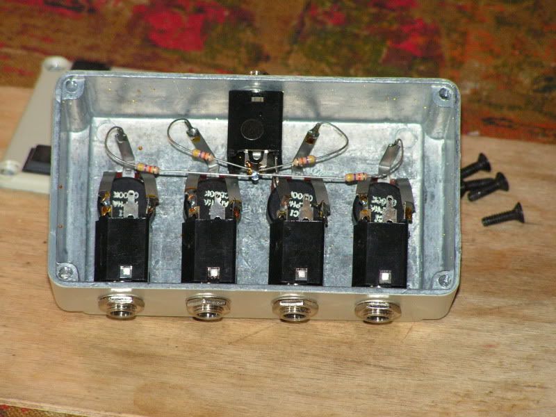
Here is a pic of the innards of my DOD.
As you can see, it is customizable.
Posted: Tue Mar 23, 2010 9:24 pm
by varice
Thanks much for the pic... It confirms for me that the box wiring is optimized as a 4 input to 1 output mixer. To optimize it for use as a 1 input to 4 output splitter function, it would need a little wiring modification.
A bit hard for me to tell from the pic and/or my laptop display - are the resistor color bands yellow-purple-RED-gold or yellow-purple-ORANGE-gold?
Posted: Wed Mar 24, 2010 8:08 pm
by Just Me
They are 47K ohm. (Orange)
Posted: Wed Mar 24, 2010 10:37 pm
by tubeampguy
This is what Bob Moog made for modulars.
Posted: Fri Mar 26, 2010 3:09 pm
by Benjamin AM
Hey Tubeampguy, thanks you so much for posting the pic. I made one of these with a 100k and it works awesome. One thing that I could not gather from the picture was where lug one was connected to.. I assumed to the housing, but when I soldered it this way there was no attenuation so I had to jump it over to the ground. Do you own any of these to check lug 1?
Posted: Sat Mar 27, 2010 5:16 am
by tubeampguy
Benjamin AM wrote:Hey Tubeampguy, thanks you so much for posting the pic. I made one of these with a 100k and it works awesome. One thing that I could not gather from the picture was where lug one was connected to.. I assumed to the housing, but when I soldered it this way there was no attenuation so I had to jump it over to the ground. Do you own any of these to check lug 1?
No I don't own these(sorry) I found this picture years ago (v.90 dial up modem) online.
The body of the pot might be isolated? Did you check it with a meter to see if there's continuity? Sometimes just the threaded area is the ground path.When its tightened down onto metal (like a control plate) It completes the circuit. You are right about pin 1 being ground. Signal comes in on 3, goes out 2(wiper) 1 is ground. 3 and 1 can be reversed to change CW to CCW.
[/i]
Posted: Sat Mar 27, 2010 4:49 pm
by Benjamin AM
Looking closely at the picture I believe that I see a wire soldered to the threading. I would take a bet that the original pots were 50k linears, that's what's used on the CP-251.
