901B Rectangular wave adjustment
Posted: Tue Jun 04, 2019 7:35 pm
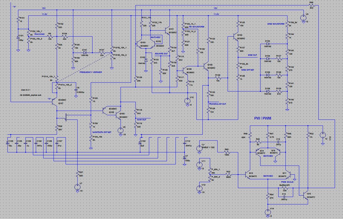
Hi, I'm trying to get a bank of 3 vintage 901B's to all have the same 50% pulse width at the same time. The 901A sends the 901B's a voltage to perform the pulse width modulation on the 901B's. The 901A is correctly sending the 0 to +12 voltage spread to the 901B's. But, the 901B's all have slightly different sounding "50"% pulse waves. Somewhere in the 40 -50 % range, instead of all being at the desired 50% pulse width at the same time. Looking at the Norlin Technical Service Manual for Modular Systems, on page 9, there is a schematic of the 901B oscillator. I don't see a trimmer anywhere for the pulse width control, like there is on the 921B's. Can someone please help me with where to place a Bourns trimmer in the 901B circuit to allow for calibration of the pulse widths? Again, the 921B's have a trimpot for the pulse width, but the 901B's do not.
I suspect a trimmer might be placed near R30 which is the first resistor downstream from connection point "C", which is the pulse width signal from the 901A.
What ohm value of trimmer should be used, and where should it be placed?
Thanks a bunch for your help,
-MoogDriver
I suspect a trimmer might be placed near R30 which is the first resistor downstream from connection point "C", which is the pulse width signal from the 901A.
What ohm value of trimmer should be used, and where should it be placed?
Thanks a bunch for your help,
-MoogDriver