Troubleshooting Old 905 Reverb Unit

System 55 • System 35 • Model 15
synthguy
Posts: 142
Joined: Wed Sep 17, 2014 7:37 pm

Re: Troubleshooting Old 905 Reverb Unit

Post by synthguy » Tue Feb 09, 2016 4:59 pm

Thanks a million! These newer pictures are a big help, and I really appreciate you taking the time to help us here at the forum!

A couple more questions, if I may....

1) At the bottom left quadrant, there's a 10uf blue cap, a 220 ohm resistor, then a resistor that I think is a 33k, but is hidden from view by the big brown .22uf cap next to it.
Could you move that cap over to the right a bit and get a shot of whatever is stuffed there?

2) Also, below that 100k resistor a bit to the right is a bunch of wires connecting out to the various jacks and pot connections. Buried under that bundle of wires, I believe that there is a bare wire jumper installed on top that connects two close by pads (below the 100k, and to the right of the 15k).
I think I can see it a bit in your current picture, but could you verify that its really there?

3) If you have an ohmmeter, could you ohm between that upper trace that the screw and big solder lug are connected to, and see if it is connected to pin2, or to pin 3 on the power connector.
I believe that this is connected to pin 3 (-6v). Lots of reverb springs have the return jack grounded to the metal chassis of the unit for shielding, while the input jacks are completely floating.
However, in your pictures, there appears to be nothing connected to the pin 3 trace, at least not on the top where we can see. There may be something soldered on the back (trace) side which I can't see.
There appears to be two wires (a green and a black one) soldered to the chassis of the reverb springs near the RCA output jack. Where do these go?
My thoughts are that there's a wire connected from pin 3 to the hole that the solder lug is soldered to, and in turn to the chassis of the reverb springs. This would supply the -6v to the reverb return "ground" shown in the schematics. There's also the chance that the green wire is the one we see coming down the connector side to connect to what I think is the ground trace at the top of the 100k. Perhaps the -6V is not used at all?
Is any of this close? :shock: This is probably the biggest question about this so far......

The 2N3391 makes sense, as Moog used lots of these in later builds, and from what I saw of the way the transistor pads are laid out, they all have the same pinout. If the transistor shown in the schematic for Q1 were used, it would have to have the leads rearranged to properly work with this layout.

Thanks again for your help! :D
Visit my synthblog...Moogs and more!
Www.synthguy.com

User avatar
noddyspuncture
Posts: 467
Joined: Wed Sep 16, 2009 7:57 pm

Re: Troubleshooting Old 905 Reverb Unit

Post by noddyspuncture » Tue Feb 09, 2016 5:13 pm

synthguy wrote:Thanks a million! These newer pictures are a big help,
Can you actually see the new photos...?
When I click the link it takes me to my own Flickr page..!

synthguy
Posts: 142
Joined: Wed Sep 17, 2014 7:37 pm

Re: Troubleshooting Old 905 Reverb Unit

Post by synthguy » Tue Feb 09, 2016 5:54 pm

Yeah, me too!
I used the original link to his flicker account, listed in an earlier post, and there they were! :mrgreen:
Visit my synthblog...Moogs and more!
Www.synthguy.com

User avatar
noddyspuncture
Posts: 467
Joined: Wed Sep 16, 2009 7:57 pm

Re: Troubleshooting Old 905 Reverb Unit

Post by noddyspuncture » Sat Feb 13, 2016 4:30 pm

Hi Folks,

I also posted this in the other 905 thread here in the Modular Forum...!

I have now extracted my 905 reverb from my cabinet and have had a look at those points for you.

I can confirm that my -6volts is indeed used and does indeed go to the output of the reverb, and also the 75uF/2.2K - 10uF - 100ohm and 82K components as shown in the schematic...!

Also the mystery "un-named resistor"... on my unit it is a small preset trimmer... and needs setting quite accurately for the recovery amplifier to actually work without being too noisey... :D

Here are some more photos of mine...
Cheers,
Tom

[url=https://flic.kr/p/E6nKMZ][img]http ... .jpg[/img]905_6 by noddyspuncture, on Flickr[/url]

[url=https://flic.kr/p/DDgi2s][img]http ... .jpg[/img]905_7 by noddyspuncture, on Flickr[/url]

[url=https://flic.kr/p/D8DKeN][img]http ... .jpg[/img]905_8 by noddyspuncture, on Flickr[/url]

[url=https://flic.kr/p/D8Z5TD][img]http ... .jpg[/img]905_9 by noddyspuncture, on Flickr[/url]

[url=https://flic.kr/p/DUWVj1][img]http ... .jpg[/img]905_10 by noddyspuncture, on Flickr[/url]

[url=https://flic.kr/p/DDgh33][img]http ... .jpg[/img]905_11 by noddyspuncture, on Flickr[/url]

[url=https://flic.kr/p/DUWUDy][img]http ... .jpg[/img]905_12 by noddyspuncture, on Flickr[/url]

Image905_13 by noddyspuncture, on Flickr

[url=https://flic.kr/p/DwTza8][img]http ... .jpg[/img]905_14 by noddyspuncture, on Flickr[/url]

[url=https://flic.kr/p/E6nHyF][img]http ... .jpg[/img]905_15 by noddyspuncture, on Flickr[/url]

[url=https://flic.kr/p/DX8B7V][img]http ... .jpg[/img]905_16 by noddyspuncture, on Flickr[/url]

[url=https://flic.kr/p/D8Z3Ea][img]http ... .jpg[/img]905_17 by noddyspuncture, on Flickr[/url]

synthguy
Posts: 142
Joined: Wed Sep 17, 2014 7:37 pm

Re: Troubleshooting Old 905 Reverb Unit

Post by synthguy » Sat Feb 13, 2016 11:57 pm

Thanks for the great pictures, Tom!

So, what's your 100k trimmer hooked to?

The 100k on the production unit is hooked between the output and ground...adjusting it low enough would eventually lower the output, but wouldn't really affect the noise.

Yours might be the Q2/Q3 feedback?

Still hoping for a few more pics of Rezin's production unit.

He's mentioned that the green wire was hooked to Pin 2 (ground) which means that the 2.2k and 75uf cap are also hooked to ground in the production units. It appears likely that the upper trace in my previous picture is tied to -6V supply, although I still haven't see the proper photo angle to confirm this.
Visit my synthblog...Moogs and more!
Www.synthguy.com

User avatar
noddyspuncture
Posts: 467
Joined: Wed Sep 16, 2009 7:57 pm

Re: Troubleshooting Old 905 Reverb Unit

Post by noddyspuncture » Sun Feb 14, 2016 7:25 am

synthguy wrote:Thanks for the great pictures, Tom!

So, what's your 100k trimmer hooked to?

The 100k on the production unit is hooked between the output and ground...adjusting it low enough would eventually lower the output, but wouldn't really affect the noise.

Yours might be the Q2/Q3 feedback?

Still hoping for a few more pics of Rezin's production unit.

He's mentioned that the green wire was hooked to Pin 2 (ground) which means that the 2.2k and 75uf cap are also hooked to ground in the production units. It appears likely that the upper trace in my previous picture is tied to -6V supply, although I still haven't see the proper photo angle to confirm this.

Looks to me that it is exactly in the same place as our "un-named" resistor in the schematic. I didn't check the value so cannot confirm if it is actually 100K.

You mentioned a trimmer in the production model..?.. I don't see any trimmers in any of the production model photos we have been shown - where did you see one...?

And if the -6volts isn't used on the production models then that means that this schematic would be one from the prototype which I have.
So there must be an updated 'production' version of it somewhere...!?

Also, although this trimmer on mine does affect the noise, there is a sweet spot - but it also is quite critical as too far either way and the recovery amp seems to shut down. Basically if it's not set correctly the unit won't work..!

Cheers,
Tom

User avatar
noddyspuncture
Posts: 467
Joined: Wed Sep 16, 2009 7:57 pm

Re: Troubleshooting Old 905 Reverb Unit

Post by noddyspuncture » Wed Feb 17, 2016 3:36 pm

Hi folks,

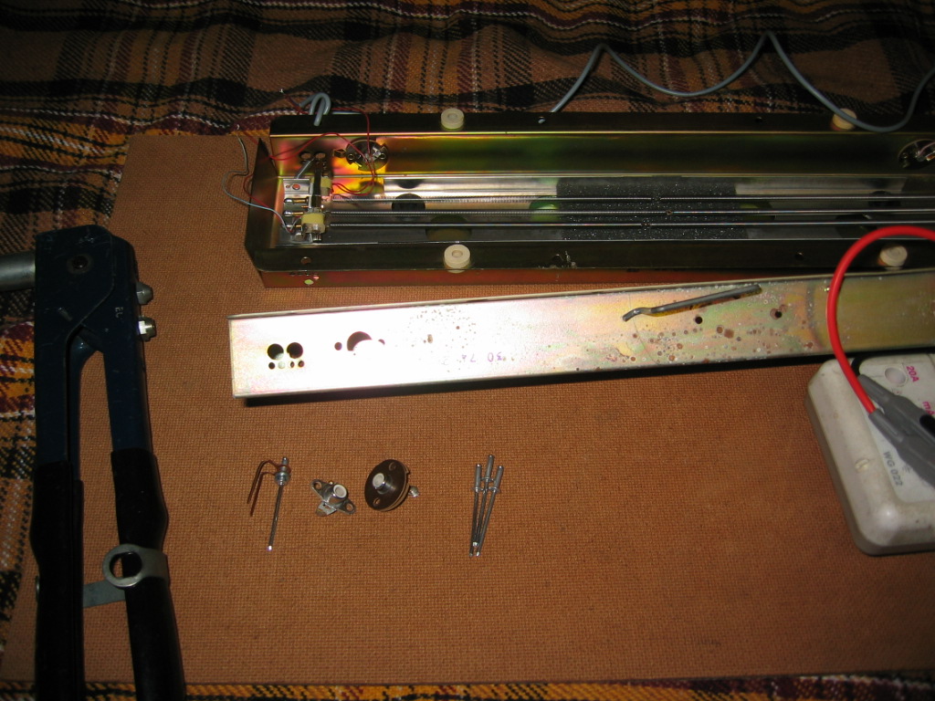
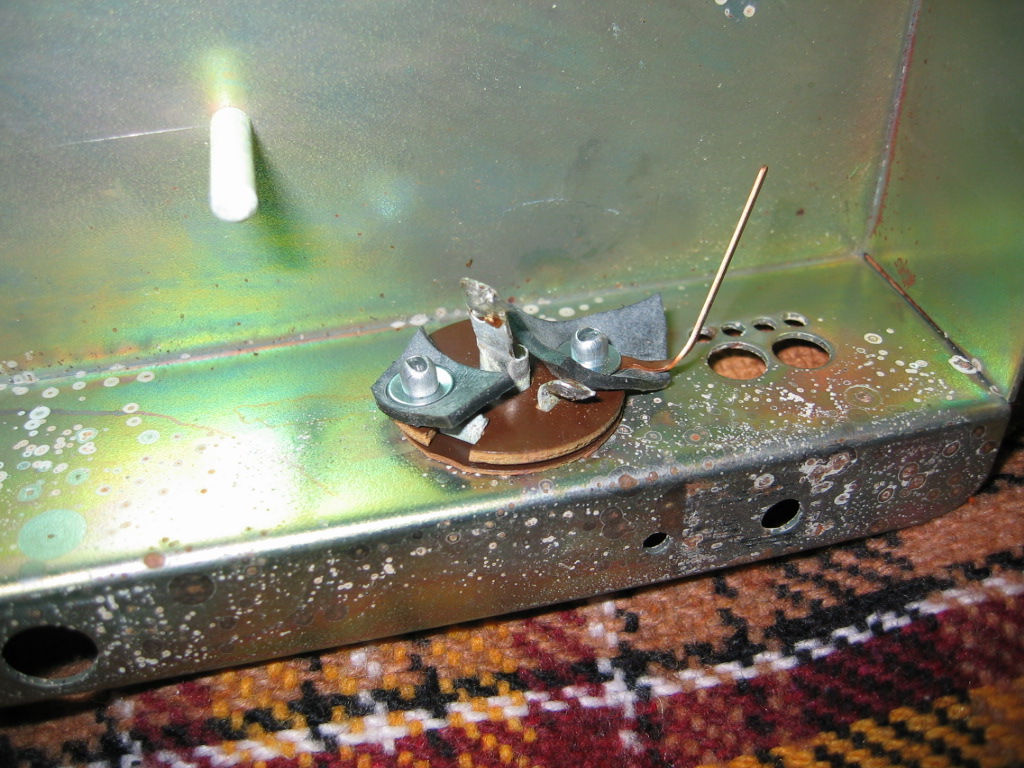
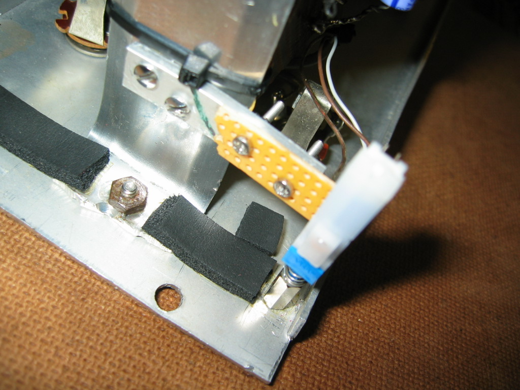
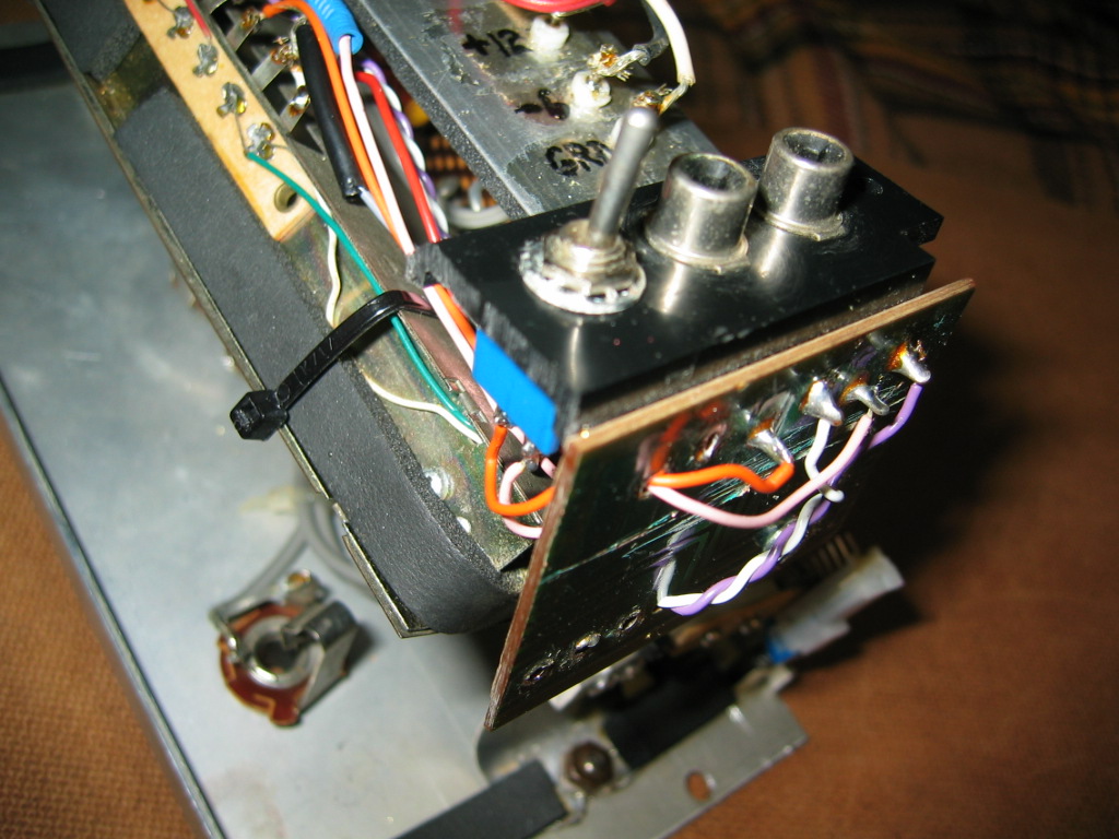
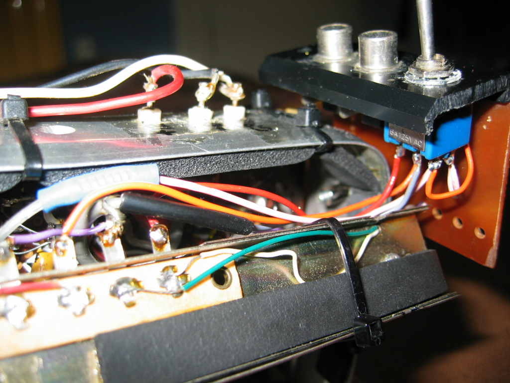
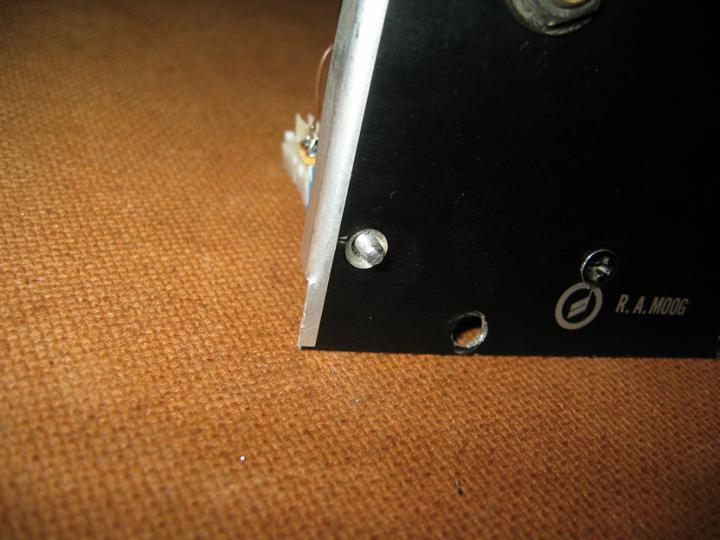
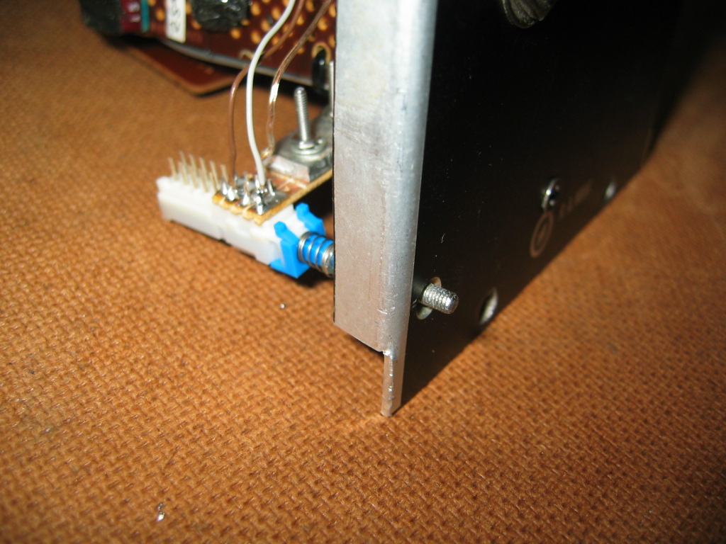
With all the recent talk about the 905 reverb and also having removed mine from the cabinet to check those requested points out - I decided to finally make the few modifications I'd been planning for it. I wanted to add the feature where the dry signal is always there and the control knob only adds the wet reverb signal to it. Although I wanted it to be switchable from the front panel, I didn't want to drill any holes for a switch - I wanted to keep the front panel original. You've seen the rear of my prototype module... it doesn't have the standard 'C' frame... but a bent piece of aluminium which only uses two of the four bolt holes to fix it. The other two holes were blanked off with some small cut-down screw heads glued into the holes..!

So I removed one of the screw heads to reveal the unused hole and I made an extension to a push switch using a small treaded bolt and fitted that strategically behind the lower un-used 'C' frame mounting hole. It works nicely and I quite like the two different options I now have.

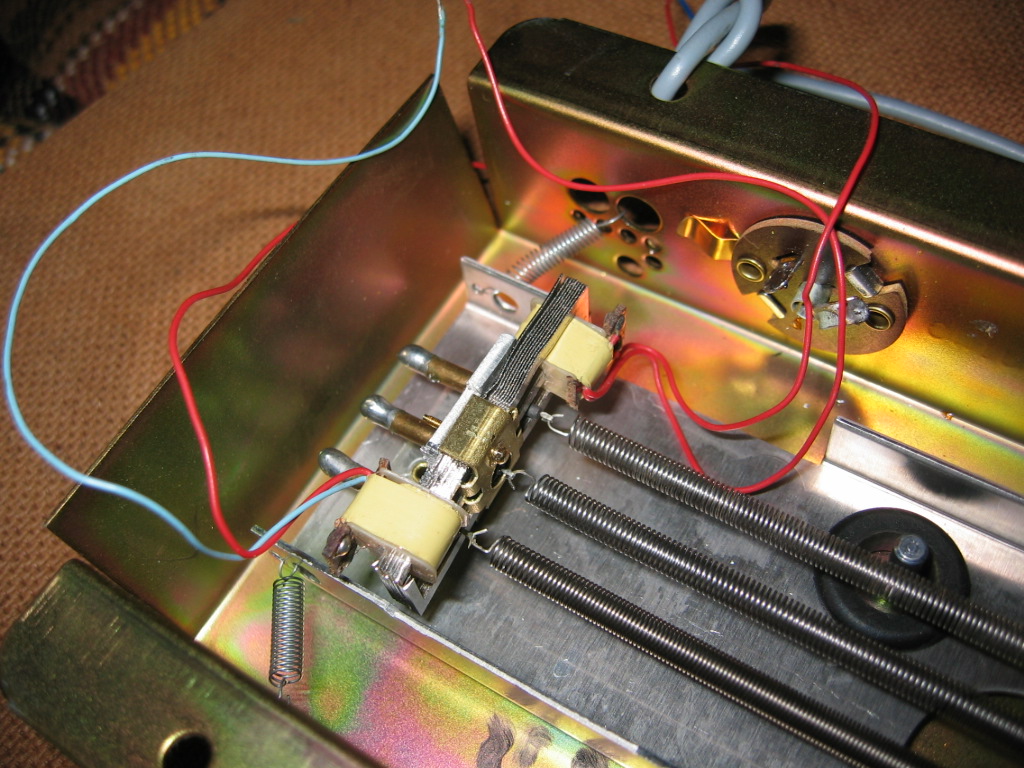
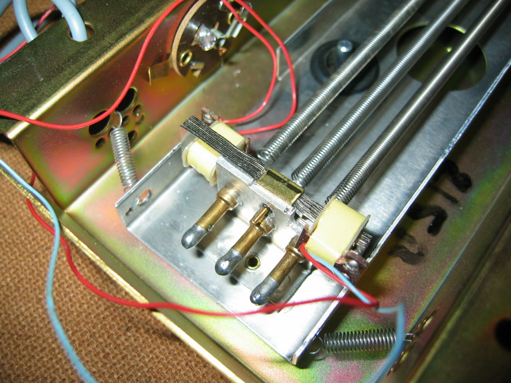
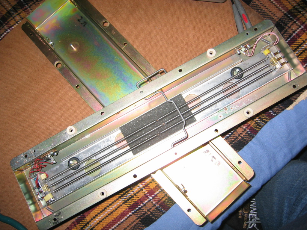
Next I decided I wanted to add another larger reverb tank, whilst keeping the original extra-small one they used on this prototype build. I made a small phono-socket panel - adapted from an old organ line-in/headphone-out panel - and then fitted a toggle switch to switch between the two tanks - the new one going to those phono sockets.

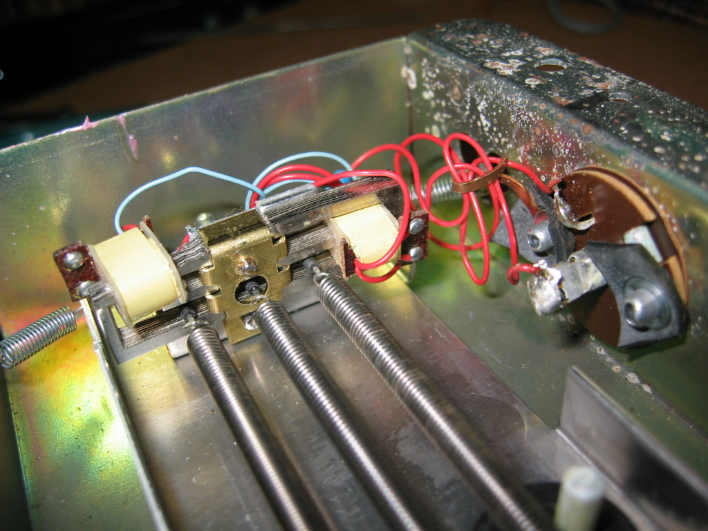
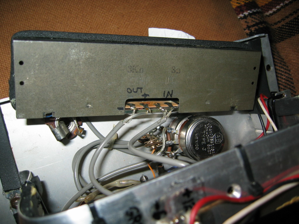
The problem I then had was that in all my collection of old "Accutronics" and other types of reverb trays, the impedances weren't quite the ones needed for the output side..! I thought long and hard and then decided to try something I'd never attempted before. I basically added another coil assembly to the laminates - took a lot of filing and jiggery-pokery - and then wired them both in series. It works a treat and the reverb I am getting is bright, full and long. Also it is a lot less noisey than the smaller one. A great addition to the small tank which is quite a lot darker and short...!

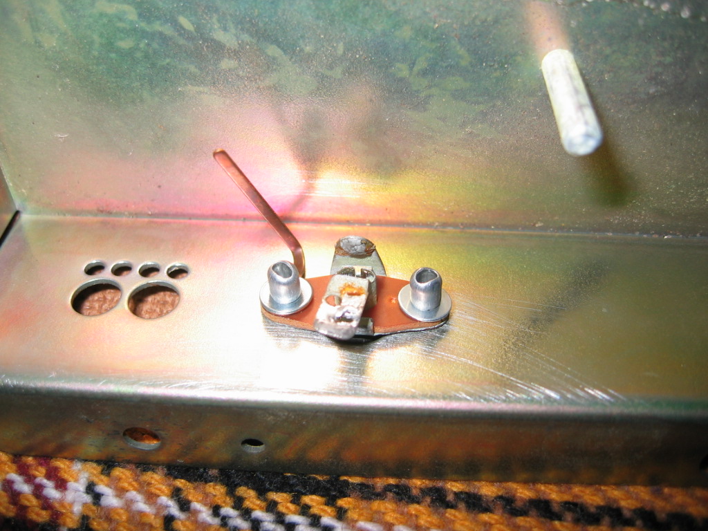
During the job I noticed that the original "Accutronics" sockets on the tank were not wired the way I wanted... output side 'ground' being connected to the casing. That meant that my -6volts would be on the case... so that needed looking at as well. I decided to change them over so the input side 0v/ground was going to the case instead.

I am going to fit this tank inside the wooden case, hanging from the top just behind the Minimoog I have in there... so I checked if it would induce any hum being nearer to the Mini's power supply...? Luckily there isn't any hum at all - so the job's a goodun'... :D

Here are some photos for you...

Cheers,
Tom

Image905_19 by noddyspuncture, on Flickr

Image905_20 by noddyspuncture, on Flickr

Image905_21 by noddyspuncture, on Flickr

Image905_22 by noddyspuncture, on Flickr

Image905_23 by noddyspuncture, on Flickr

Image905_24 by noddyspuncture, on Flickr

Image905_25 by noddyspuncture, on Flickr

Image905_26 by noddyspuncture, on Flickr

Image905_27 by noddyspuncture, on Flickr

Image905_28JPG by noddyspuncture, on Flickr

Image905_29 by noddyspuncture, on Flickr

Image905_30 by noddyspuncture, on Flickr

davebr
Posts: 15
Joined: Sat Jan 18, 2014 5:38 pm

Re: Troubleshooting Old 905 Reverb Unit

Post by davebr » Tue Apr 05, 2016 2:25 pm

I have some photos and a corrected schematic on the 905 I restored. You can email me if you want higher resolution photos. Email is on the home page.
http://modularsynthesis.com/moog/905/905.htm

Dave

Post Reply