racking the fooger collection

Yes, you would be modding the patchbay, not the 'fooger.


Above is how you would wire a socket. In an off-the-shelf PB the situation will probably be more complex than this, as there are additional traces on the PCB so it “knows” what you plug in and which configuration you need.

The operation is pretty simple: pins 1, 2 and 3 represent the normally closed switch contacts. 6, 5 and 4 are the T, R, S contacts, respectively. When no plug is inserted, the switches are closed and the signals flow to/from pin 1<>6, 2<>5 and 3<>4. When a plug is inserted, the signals instead flow to/from pins 6, 5 and 4 to the T R S plug and are disconnected from 1, 2 and 3.

So for the 104, an expression signal is represented by

6: CV/“resistance” (input)
5: +5 VDC output (supply)
4: ground

And to “normal” your connection, you need to send the signal hitting pin 6 through a 100k resistor to ground, ONLY IF there is no plug inserted. No plug means pin 6 is connected to pin 1.

So connect pins 1 and 4 with a resistor, the input will be clamped to ground when you need it. Insert a patch cable and the resistor is out of circuit.

your spear of wisdom has pierced my brain. and I thank you for this.

i’ll let you know what the patchbay circuit looks like. should be a flawless victory.

custom rack case in the house.

wiring everything up over the weekend. huge order from redco coming on tomorrow!

oh yeah, that empty space on top… it’s for a slim phatty.

and on the floor… an mp-201. life is good.

Wow!

I want one… Where did you get your flight case made and to what specifications..? Let me know how you get on with your wiring / soldering shenanigans.

Peace, love and flowers…

a&s case company in north hollywood. i could get you specs if you need. could be a bit smaller, but i wanted room for the power supply.

Nice looking case ( I just couldn’t bring myself to say Nice Looking Rack). Thanks for posting the photo. A Sp will top it all off nicely.

Slabwax

here’s what the pcb from the patchbay looks like. not sure how to get the 100k resistor to do its job.

also, i should be running most of the cv stuff in the “isolated” configuration, right?

the murf is acting weird. it’s like the mix is all the way down when it’s plugged into the patchbay. might need the resistor on these inputs as well?

also, the freqbox is giving me some strange noise like it’s being modulated by something. the wave seems to jump randomly.

i need to step away for a moment, i’ve been piecing this together and soldering for 2 days straight.

Hi SeanK

Sent you a Private Message - good luck with the rest of your soldering shenanigans.

Peace…

Hi Sean, let’s keep it public so others may learn from your troubles ( ?)

Perhaps upload a close up photo and it might be a bit clearer. It looks like some sockets are non-switched. You’d need to use a switched one for this to work.

Sounds good.

First off, check your soldering, you may have a short somewhere. When you use an expression pedal on any of these CV inputs, the knob must be turned to halfway. I’ve used a patchbay with my MuRFs; no problem from memory.

Try powering from a separate wall wart and see if the issue remains.

That’s usually a good idea. :slight_smile:

P.S. case looks really good so far, I hope everything works out properly in the end.

just in case you can’t make it out: in the top photo, the grey jack is on the top left.

i’ll post schematics/dimensions for the case when i’m all done with everything.

okay, just tried a resistor from tip to sleeve on a dummy plug and plugged it into the “mix” of the delay on the patchbay and it did not work. when i plug in my expression pedal, it works perfectly. i’m going to try a jumper wire instead.

thanks again for all of your help!

got it! just started touching resistors to the tip, ring, and sleeve contacts on the patchbay pcb’s and figured it out. so nice to have everything wired up and fired up. making a nice colored, laminated label that goes over the front of the patch panel right now.

next on the list: slim phatty up top.

I made holes in the wooden ends and screw them together

here’s a little preview. i’m going to post the template, case dimensions, glamour shots and other stuff once the slim phatty is in there and wired up.

seank

That patch bay overlay looks great. NICE JOB Please do post the templet.

yeah, 2nd that on the template. I’ve started to build something very similar. I’ve tested all my pedals, I just want to make sure I put the right resistors in. I’m going to try and build the patch bay from scratch, which may make adding these things a little less complicated.

okay, here’s the template. so:
print to exact size (19" wide) then laminate. note: this is sized for a neutrik trs patchbay.
trim the plastic edges.
use a grommet hole punch to make all of the holes.
use photo mounting tape on the laminated template.
carefully adhere to the patchbay faceplate.

http://imageshack.us/f/710/patchpanelcolormultiple.jpg

seank

Thanks for the link

posting this here so everyone can benefit (pm from noSpoonMusic):

"Ive been following your rack case build. Well done. I had been toying around with different ways of doing this for a while and you took a great approach. How heavy is it? Also, can you tell me which connections you added resistors to? And what kind of resistor? I’ve gone through and tested all my foogers.

When I connect the Osc out to Osc in on the Ring Mod, the sound gets a little brighter than without patching. Any cure there?

The MidiMurf gives me slightly offset sounds when I patch into the rate, mix, envelope, and lfo/sweep. Im assuming these all need some kind of resistor. The amount of offset is slightly different on each, would using different resistors help this problem?

I also get a change in value when I patch the env amount on the Freq Box and the sweep in on the Phaser.

How did you address these issues. . .if you even had them at all.


Thanks"


so first off thank you. it was a lot of work.

the case is pretty heavy. i wish i would have sprung for the flyweight (expensive but super light material used instead of plywood). seriously, it’s totally worth it. a&s case company in north hollywood has all of these dimensions on file so they could easily make you one. mine was $450, but it would be a good deal more for the flyweight.

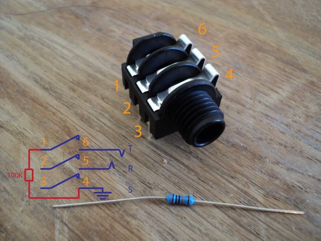
so yeah, a few things need to be normalled, ring mod carrier out to carrier in is one of them.

almost all of the murf and delay inputs (delay loop out to loop in just needs to be normalled) needed resistors. i can’t remember which inputs or the values of the resistors. honestly, i was just touching them to the contacts until i got it right. the murf knobs are different when it’s patched to the patchbay or when an expression pedal is used. it assumes that 12 o’clock is zero. it’s strange, but not really a bad thing. latigid has a thread that explains a lot of this stuff in greater detail. a lot of that info has been included in my thread.

a voodoo lab pedal power 2 plus will take care of everything. all pedals need the white barrel positive center cables, the freqbox needs a current doubler (y-cable adapter) and the murf and delay need to be plugged into the higher current outputs (5 and 6). the slim phatty will take the standard 120v outlet. it’s pretty much perfect. one power plug to the wall and you’re done! you’ll need some l brackets to mount the box to the back of the moogerfooger rackmount kit.

making 52 trs cables is not fun. you’ll need about 150’ of mogami w2549 balanced mic cable, 52 stright jacks, 48 right angle jacks, and a cable tester. also, netflix and snacks.

slim phatty next week, then i’m totally ready for synth sleepovers.

instead of using different resistors for each connection (that requires one) could I use a trim pot?